Building The Automatic Table Saw
After 10 years of service my first built table saw was due for an upgrade. I have been salvaging parts for years, not specifically meant for this build, but mainly for some future projects.
My day job is at a production plant for wood panel production. Over the years a lot of the machinery has been replaced og discarded for poduct line changes.
So it is not unusual to bring home stuff that was picked from the trash or menat to go to the scrapyard.
Some of these things have now risen as my new tablesaw.
My old saw was lacking trunnions, and was getting somehow a little sloppy.
So on version 2.0, I went all the way.
The goal was to make the trunnions out of wood, and just see where it was going on the build.
Most of my builds have been designed along the way, as I have a vision, but the execution is more “on the fly”
This build took place over approx 4 months, and due to the above mentioned reason, I did not shoot a video of the build as I was kind of figuring out the design along the way.
It is hard to have to consider camera angles and detail coverage along with figuring out how to actually solve the problem.
The old saw had to be stripped down to the bones as the motor and arbor was going to be reused.
I took some shots of the process:


I started with the heart/center of the saw. The saw carriage.
It is built fro baltic birch plywood, mainly 18mm but also some 12mm.

The actuator is installed at one of the sides, and has a mounting block to keep it parallel to the sliding inner box.

The “inner box” is running on some SKF 20mm linear rails

The motor mount is also made from 18mm plywood.

The Trunnion grooves was cut 15mm deep in a sheet of BB 24mm thick

Unfortunately I did not have any image of the trunnion arcs/slider. But they are made from a 26mm thick phenolic sheet. This creates a gap between the side of the trunnion and the sawbox, making it garder for dust to pack.
The trunnions are tested in the frame for the first time.

The bottom of the saw box got some holes for dust to escape, if it did not get cauhgt by the DC. i later opened this up to a full opening, as there was some accumulations on the bridges between the holes.

Then it was on to install the actuator and ballscrew for the tilt. The ballscrew for the tilt is actually a butchered actuator motor and a 12mm ballscrew I had laying around. I machined some thrust bearing holders from aluminum, and it worked great.

It is located in a separate compartement, so that it would be easier to keep the dust contamination to a minimum.
The frame is built from extruded aluminum profiles in different sizes. I also made an addition on the far side in this image, to house the control cabinet, and to also give support for the top

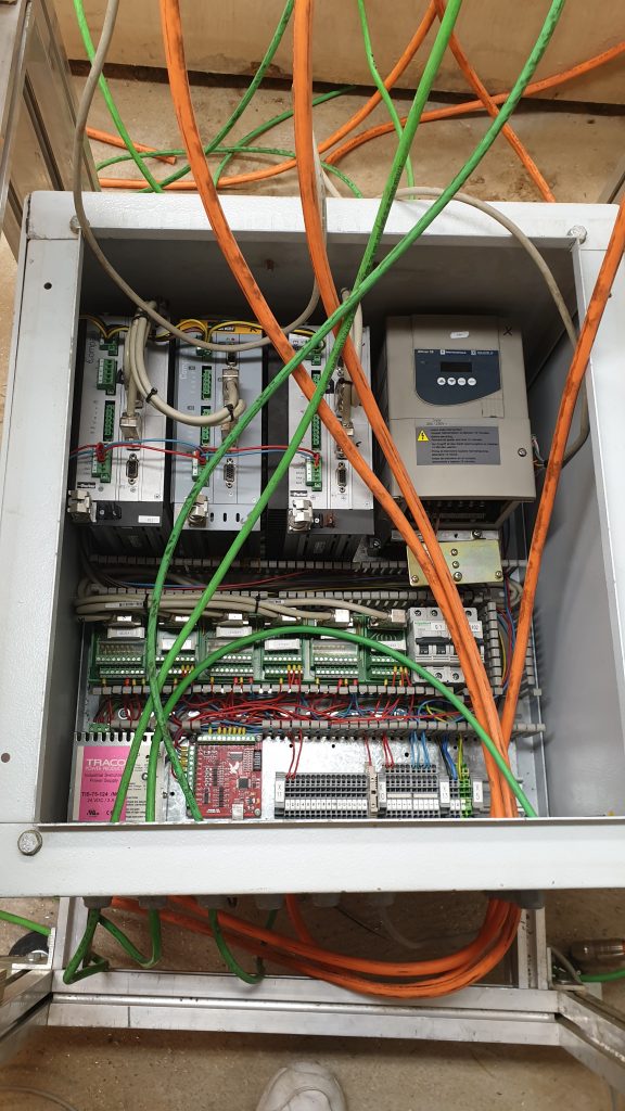
Speaking of the control panel. It was a little overloaded, but I installed a cooling fan to keep the temperature down.

Then it was time for some soldering to extend the sensor cables and so on.

The linear unit for the fence wa build from a 100mm x 100mm extruded aluminum, with 2 pc 20mmm skf linear rail on top. these where aligned with the same method I used with a dial caliper on the cnc build

The timingbelt and carriage under installation.

The unit for the fence is bolted to the frame with full adjustment options in both up/down and in/out.

The top is a 28mm particle board with a high pressure laminate on it. I chose this one specifically due to the structured surface. this helps tremendously with low friction. I cut the recess and hole for the insert plate with the cnc.

The CNC was also used to cut the vent holes for the motor cooling fan. It was placed a little to close to the side panel. actually so close that I had to make a recess for it.

Here is a shot before the side panels was painted.

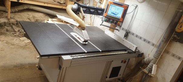
The boom arm for the overhead dust collection was made from 9mm baltic birch plywood, and webbed to make it lighter. I actually forgot to insrt the pipe before I glued it together…..big mistake, but I managed to get the elbow connector installed anyway.

The articulating arm for the monitor was constructed by using a 44mm x 44mm extruded profile inside a plywood box, and some nylon screws as friction points. This made a great telescopic arm.

The monitor is actually a complete all in one computer that was used for a terminal on some forklifts. It is recessed into the panel and the handle is actually a reused curtain rod:)

The only thing I had to purchase was the motion controller.
It is a 5 axis USB controller designed for Mach 3. It is a little bit different form your standard 5 axis mach3 breaokout board that is used with a parallel port. This only has 4 inputs and 4 outputs, but is capable to pulse at 100Khz. It is pretty inexpensive with a price of approx 15 usd.

With the limitations in inputs and outputs, the limit and homing switches needs to be wired in a little different way than “normal” But it works for me.
The control screen is a custom made screenset for the Mach3 software. It was designed using Klaus´s machscreen designer. It was a huuuge time thief. I do not dare thinking of how long this took to set up. There are still some functions that needs to get added, but that is a subject for future projects.

All in all I am very pleased with the result, but it took a lot longer than I had imagined. I guess somewhere around 200 hrs +….at least.
Here are some specs on the build.
3 hp saw motor
1800mm x 1200mm table surface (w/wing extension)
95 mm depth of cut capacity.
950 mm rip capacity.
0 – 47 degrees left tilt.
3 axis full servo powered positioning.
12.1″ Touch monitor.
Finishing of with some full frame shots.


Hello
Your work is amazing
Are you planing to sell the plans to build this saw?
I am interested
Thank you Victor. No I am not planning on releasing plans for unfortunately. If someone was to purchase all these parts new (and not salvage them) it would be way better to buy a commercially built saw. But thanks for the interest
Hi Victor.
Thank you Sir.
There are no plans avaialable for this one. This is all built ofsalvaged parts, and I think if I was to purchase all the parts it would be waaaaay to expensive, and comparable to a commercially made one.
Sorry about that
BR
R
Hello Luis.
Thank you for your interest.
The saw was built using salvaged parts, and are designed to fit these. Some of the parts are 20 years old, and probably not vailable any mor.
So there will not be made any plans available unfortunately.
Hi Mark, and thanks for the interest.
The screenset for the table saw is not complete yet, unfortunately.
I have made a custom screenset for a fence position setup for the miter saw.
But due to a copyright issue, I am not able to share this.
Sorry about that
But it is not that hard to build your own screenset using machscreen designer by Klaus
Thanks Julio
I have sent you an email
Thank you Dough
The screenset is still in devopement mode, with several bugs, so I am not able to share it atm.
SOrry about thet.
BR
Roy
it’s a great work with table saw love that keep it up. Thanks!
Thank you
Best reg
Roy
Thank you Ali
There are no plans avaialable for this one. This is all built of salvaged parts, and I think if I was to purchase all the parts it would be waaaaay to expensive, and comparable to a commercially made one.
Sorry about that
BR
R
Thank you very much Hector.
Srry for the late reply, and thanks for contacting me via email previously
have a great day Sir
Best reg
Roy